Abstract
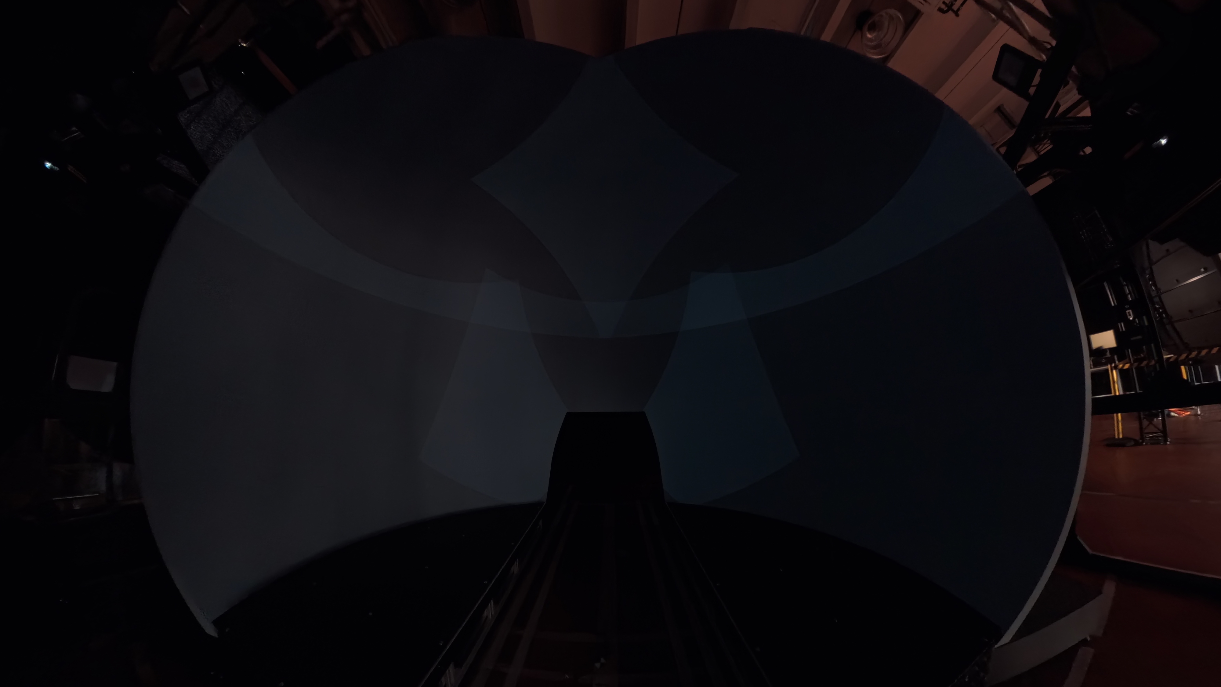
Multi-projector systems solve coverage, brightness and field-of-view requirements by combining several optical channels. The same overlap that makes seamless blending possible, however, can make dark content reveal the limits of projector black level. When two or more projectors illuminate the same screen area while displaying black, their residual optical output can accumulate. The result is often a visible increase in luminance in overlap regions and, consequently, seams or patches that are especially conspicuous in night scenes, simulator imagery, planetarium content and other low-luminance applications.
The central point is important: software cannot make a projector emit less light than its physical black state. Instead, black-level correction can raise the black floor of other regions so that the display approaches a common spatial luminance baseline. This trades some overall contrast for spatial uniformity. Optical black-level masking can preserve more contrast, but it requires installation-specific hardware and is less flexible.
VIOSO Projection Tools is particularly well suited to this problem because black-level correction is integrated into a broader camera-based calibration workflow. The strongest technical case for ProjectionTools is it can measure and compensate the spatial consequences of non-zero and non-uniform projector black levels within the same calibration model used to align and blend the complete multi-projector system.
1. The Physical Problem: Black Is Not Zero
A digital black command such as RGB = [0,0,0] is an input state, not a guarantee of zero optical output. Projector architectures have finite contrast and residual light caused by the optical engine, imaging device, stray light, internal reflections, imperfect modulation and other implementation-dependent effects. The measured black level therefore depends on the projector, operating mode, optics, light source, temperature, calibration state and measurement geometry.
In a multi-projector system, the screen luminance produced by different projectors is approximately additive when the projected light is incoherent and the screen response is treated in the usual linear radiometric sense. A useful first-order model is:
L_black(x) ≈ Σ_i a_i(x) · B_i(x)
where B_i(x) is the black-state luminance contribution of projector i at screen position x, and a_i(x) represents the local contribution of that projector after geometric mapping, blending and any optical attenuation.
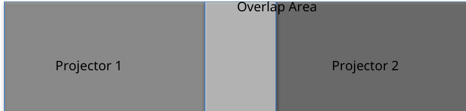
The consequence is a spatial black-level discontinuity. A single-projector region may have a lower black floor than a two-projector overlap. In a dark image, the eye can detect this discontinuity even when the absolute luminance is small.
2. What Software Black-Level Correction Actually Does
Software black-level correction does not subtract the overlap light. If a projector produces residual light in its black state, an ordinary video pipeline cannot command a negative luminance to cancel it.
Instead, the practical software strategy is black-level uplift: raise the minimum output in regions with a lower black floor until the spatial black floor is closer to the highest required level in the compound projection.
In simplified form, if the target black floor is T(x) and a projector contributes a measured black level B_i(x), the correction seeks an output transformation such that:
B'_i(x) ≈ T(x)
subject to the projector's available output range and the constraints of the color and transfer functions.
The important engineering trade-off follows directly. Raising black in the darker regions makes the display more uniform, but it also raises the minimum luminance and therefore reduces the maximum achievable dark-to-bright contrast in those regions. Black-level uplift is consequently a uniformity optimization, not a method for increasing native contrast.
3. Why Measurement Matters
A black-level correction map cannot be derived reliably from projector specifications alone. The correction depends on what the installed optical system actually produces on the screen.
A robust workflow therefore needs to establish, at minimum:
- the geometric mapping between each projector and the physical screen;
- the actual overlap topology;
- the measured black contribution of each projector;
- spatial non-uniformity within each projector's field;
- color-channel differences where colored black correction is required; and
- the final correction in the coordinate system used by the rendering or playback pipeline.
Camera-based calibration is valuable because geometry and photometry can be related in a common spatial model. VIOSO describes ProjectionTools as a camera-based calibration suite that generates data for warped and blended multi-projection systems, with corrections for color, black levels and other parameters.
4. Multiple and Higher-Order Overlaps
Higher-order overlaps are one of the places where a simplistic black-level explanation breaks down.
If three identical projectors each contribute the same black luminance B to a screen point, the first-order sum is 3B. But in a real blend the contribution is spatially weighted. The correct target is therefore determined from the measured compound contribution rather than from the overlap count alone.
This matters at intersections, corners and complex dome layouts. A correction method that assumes only binary single-versus-double overlap can leave residual steps in areas where three or more channels contribute.
VIOSO black-level correction based on projector uniformity and contrast measurements and notes smooth black-level transitions for overlaps, even involving more than two projectors. This is a meaningful differentiator because the practical problem is not merely identifying whether a pixel is 'in overlap'; it is determining a spatially appropriate correction across a compound optical system.
5. Chip Oversize, Pond of Mirrors and Edge Light Leakage
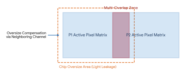
Projector imaging devices do not necessarily produce a perfectly sharp optical boundary exactly coincident with the addressable image raster. Depending on the projector architecture and optical design, light can originate from regions outside the intended active image area or from stray-light paths around the imaging aperture. This can create edge halos or boundary artifacts that become especially visible when one projector's image border falls into another projector's field.
In DLP projectors, the active DMD array is surrounded by a non-addressable border of mirrors commonly known as the Pond of Mirrors. These mirrors are permanently held in the off state during operation. LCD and LCoS architectures may exhibit comparable inactive-border or stray-light effects, although their physical construction and terminology differ.
the chip oversize area. The physical mechanism and terminology may vary by projector architecture and manufacturer.
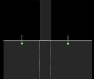
ProjectionTools addresses chip oversize through automated spatial compensation (Figure 3):
- Oversize Boundary Detection: The calibration software identifies the physical boundaries of the light frame during opticalmeasurement.
- Adjacent Channel Compensation: ProjectionTools calculates where an unaddressed chip oversize band from Projector A falls onto the screen and commands the overlapping active pixels of Projector B to lift their local black level, neutralizing the visible boundary contrast seam.
6. Intra-Projector Spatial Non-Uniformity in Luminance and Color
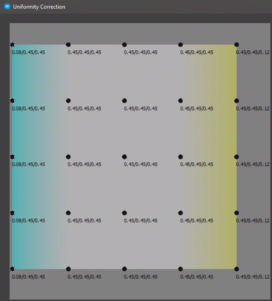
Black level is not necessarily spatially constant within one projector. Lens vignetting, optical geometry, projector-to-screen distance, incidence angle, internal stray-light paths and other effects can produce a spatially varying black floor.
This means a single scalar 'black level' per projector is often insufficient for high-end installations. A spatial correction map can better represent the actual system:
B_i = B_i(x,y)
and the desired correction can likewise vary across the image.
VIOSO technologies documents black-level correction based on measured projector uniformity and contrast, as well as floating-point precision in blending and black-level calculations. It performs precise corrections of color, black levels and other parameters as part of the calibration workflow.
The black floor is not guaranteed to be spectrally neutral. Residual light can differ between red, green and blue channels because the optical engine, light source, filtering, modulation and internal stray-light paths have wavelength-dependent behavior.
For this reason, a correction that equalizes only luminance may still leave a colored seam. ProjectionTools incorporates spatial per-channel, per-RGB color correction on black. This neutralizes color tints and ensures uniform color temperature across dark scenes.
7. ProjectionTools: From Calibration to Black-Level Optimization
The practical advantage of VIOSO ProjectionTools is that black-level correction is not presented as an isolated video trick. It sits inside a complete calibration chain.
ProjectionTools uses camera-based measurement to generate calibration data for multi-projector systems. VIOSO describes support for flat, cylindrical, spherical, dome, cave and arbitrary 3D projection surfaces, with workflow components for creation, mapping, 3D mapping, pattern generation and alignment.
For demanding installations, this integration matters. A black-level map only has value if it is registered correctly to the same physical screen coordinates as the warp and blend solution. If projectors move, the geometry changes; if geometry changes, the overlap regions change; and if the overlap regions change, the black-level correction must remain spatially registered to the new configuration.
ProjectionTools is therefore best positioned as an installation-aware calibration platform rather than merely a black-level filter.
8. Conclusion
Black-level artifacts are a fundamental photometric problem in multi-projector systems. They arise because projectors do not produce zero optical output in their black state, and overlapping channels can accumulate residual light. The correct engineering response is therefore not to pretend that software can create a darker-than-physical black, but to measure the installed system and optimize the spatial black floor.
Achieving seamless low-luminance visual fidelity in immersive multi-projector environments requires rigorous algorithmic handling of residual light. While optical hardware blends address raw overlap intensity, VIOSO Projection Tools delivers the industry's most comprehensive software solution. By combining automated multi-overlap calculation, chip oversize compensation, 2D intra-channel spatial luminance balancing, and per-RGB color offset mapping, Projection Tools guarantees a particularly comprehensive and technically mature toolset for the job